• Hey there Guest!
    If you enjoy BCF and find our forum a useful resource, if you appreciate not having ads pop up all over the place and you want to ensure we can stay online - Please consider supporting with an "optional" low-cost annual subscription.
    **Upgrade Now**
    (PS: Subscribers don't see this UGLY banner)
Tips
Tips

PCV Valve, Jumping in With Both Feet

vette

Darth Vader
Country flag
Offline
I'm going to jump in here with both feet and stick my neck out real far so you all can cut it right off.
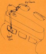
In finishing up my engine installation I have been looking at the possible installation of a PCV valve. I'm going to try to attach a drawing representative of the factory crankcase ventilation of my BJ7. Just for reference. To be honest with you I don't see how it could work. On contemporary engines and I believe on all engines, if there is a hose going from a valve cover to the air cleaner, this is the air inlet into the crankcase. This is not suction, but air inlet. The hose going from a valve cover , with a PCV valve in it, to the intake system "BELOW THE THROTTLE PLATES" is the suction. It you are going to draw air out of the crankcase you have to have another openning to the crankcase to allow air in so that there is a free exchange of atmosphere. As you can see on a contemporary engine, the hose stuck into the air cleaner is the air in, and the hose (with the PCV valve) stuck into the intake manifold below the throttle plates is the atmosphere being pulled out of the crankcase. So noting in the pic that the openning in the side tappet cover is plumbed to the openning at the top of the valve cover and then via the " T " plumbed on to the air cleaner, since that is air in, where is the circulation by air being drawn out. One last thought, "the best crankcase ventilation is no crankcase at all". Ok, boys: I'm holding my head, swing away. Dave.
 

Attachments

  • PCV-1.jpg
    PCV-1.jpg
    12.6 KB · Views: 160
Country flag
Offline
I have the 'kit'--it was just the valve, a gasket for the dipstick and instructions (might have had a barbed fitting for the manifold--from BCS installed in my BJ8. At idle, there is a vacuum at the oil filler hole on the valve cover. Whatever air gets in is likely mostly drawn past the reverse screw at the rear main 'seal.' The valve reduced oil consumption by nearly 100%; from a qt. every 1,000 miles to every 2,000 miles. I've probably got close to 50K miles on the setup with no negative consequences (that I know of). I do run the rear carb a tad richer than the front.
 

healeyblue

Jedi Warrior
Gold
Country flag
Offline
couldn't you plumb the vacuum via the PCV valve to the tappet cover and the fresh air via the air cleaner to the valve cover, eliminating the "T" by capping one side, thus causing a circulation through the engine and an exchange of fresh air for oil vapor.
 
OP
vette

vette

Darth Vader
Country flag
Offline
Healey Blue, your idea makes sense to me. Because putting the PCV valve in tubing from the tappet cover to the intake manifold fitting would cause a suction to be drawn on the crankcase. And an openning at the top on the valve cover would allow fresh air in weather it be a hose over to the air cleaner or not. I've attached another pic of another possible configuration.
Bob, I undersdtand what you are tellling me. I would have to believe that if you put either one of your original hoses plumbed into a fitting on your intake manifold with a PVC valve that you would have to be pulling a vacuum on your crankcase and that would very likely go a long way to keeping oil from seeping out the rear main seal.
I think what I am getting out of this so far is that I believe that in the original configuration there may be somewhat 'MORE' pressure in the crankcase than necessary. Because if you look at my first drawing I don't see how you could not have some pressure because there is only one hole/openning/one way in to the crankcase and that is pretty restrictive. It would be pretty impossible to have any circulation. So my original question 'how could it work' I think the answer is Not Very Well.
So my next question is, Is pulling a vacuum as in the way Bob has it plumbed better or worse than the configuration that is shown in my second pic. (attached here). The configuration in my second pic would be pretty much identical to an early system where road draft tubes were common place. Because the air inlet was at the oil filler cap with a vented/filtered cap. Dave.
 

Attachments

  • PCV-4.jpg
    PCV-4.jpg
    12.5 KB · Views: 128
5

57_BN4

Guest
Guest
Offline
Dave- yes the factory setup is kind of illogical. I am fairly certain that it is this way because DMH or somebody disliked the fumes smell that comes from the road draft tube and perhaps to satisfy an urgent request to get rid of the smell, the engineers simply deleted the draft tube and added a pipe up to the rocker cover. For all it is good for, they could have just as easily welded up the side plate hole and left only the r/c breather. Below is a pre-production press photo of a 100/6 in 1956 showing an A105 sedan engine installed which still has the road draft tube as per the sedan setup.
Press photo A105 engine 1956 engine.jpg

Fitting a PCV with no filtered air entry point on a 'tight' engine will risk having negative 10 psi pressure in the crankcase when descending a long hill engine braking since the plunger in the valve will relax and allow a direct connection from the sump to the intake manifold. It will also draw in unfiltered air through any leak points.

If your engine is rebored and gets run-in properly then the factory system is perfectly adequate for eliminating fumes smells. Technically it is better to have fresh air circulating through the crankcase to control the oil acidification as per modern cars.

If you wanted to keep it looking original then you could plug up the pipe between the side cover and rocker cover and weld a hose barb onto the back of the side plate pipe so the PCV valve draws fumes out (of where the road draft tube used to go) and the original air cleaner pipe lets fresh filtered air in to the rocker cover. Be aware that the amount of oil exiting the engine via the draft tube was quite high since there is no real coalescing filter there. On my Ford I did exactly this modification and ended up welding in a box of sorts to the inside of the side plate which is stuffed full of steel wool scouring pads that catch oil mist before it goes into the intake air.

Out of interest, here is a pic of the factory sedan setup. This is an original 3000cc engine in a 1962 Wolseley 6/110 which still used the two H4 carbs and gallery head. The black tube goes to the common intake plenum/filter that both carbs share. Again, somewhat illogical and perhaps reflective of the state of engineering in BMC at the time- they could have just specified the Healey breather parts.
wolseley breather.JPG

Andy.
 
OP
vette

vette

Darth Vader
Country flag
Offline
Thanks, Andy. I've considered all these options and at the moment don't know which way I will go. I believe that a free breathing crankcase is the most efficient configuration. And I believe this is accomplished with a road draft tube. But I am concerned about the smell and the possible oil loss drawn thru the tube. I am also concerned that a stand alone filter at the top of the rocker cover could also spew some oil. My rear carb always seemed somewhat dirtier (carbon fouled) when I drove the car with the stock configuration. So that is what I hope to avoid. Bob's PCV system seems to be giving good results. But a non-ventilated crank case somehow troubles me. Whether it be one with vacuum or pressure. So at this point it's time to make a decision. Thanks all for your help.
One last interesting tidbit. I am currently reading a book titled, "SHELBY COBRA FIFTY YEARS". On page 106 the caption under a picture of a ventilating hose on one of the 427 engines says "Here is the extent of emission control equipment on a 427 Cobra. A breather hose runs from the crankcase oil cap to the rear air cleaner to keep crankcase vapors, containing unburned fuel, from hitting the atmosphere. This niffty "spark arrestor" (my quotations marks) seen in the picture is installed in the hose to prevent a carburator backfire from hitting said vapors in the crankcase and causing an explosion." Hmm.
Dave.
 
5

57_BN4

Guest
Guest
Offline
Hi Dave, if you have just reconditioned the engine maybe try the factory setup for a bit and see if the lack of 'huffing' from the properly sealing rings obviates the need for extra equipment?

The amount of huffing is related to how well the rings seal so have a read of some 'running in' posts on other forums as there is plenty of controversy. After warmup and cam break-in, I ran mine hard and fast on the dyno- up to the redline at full throttle then back right off and fast-idle for a minute. Repeat a dozen times and change oil. That is approximately how OEMs like Porsche do it, then give to the customer to drive gently for 500 miles.

Result is virtually no fuming from the breather using Total Seal Gapless 2nd rings as per Randy F's suggestion.

Andy.
 

steveg

Yoda
Gold
Country flag
Offline
I have the 'kit'--it was just the valve, a gasket for the dipstick and instructions (might have had a barbed fitting for the manifold--from BCS installed in my BJ8. At idle, there is a vacuum at the oil filler hole on the valve cover. Whatever air gets in is likely mostly drawn past the reverse screw at the rear main 'seal.' The valve reduced oil consumption by nearly 100%; from a qt. every 1,000 miles to every 2,000 miles. I've probably got close to 50K miles on the setup with no negative consequences (that I know of). I do run the rear carb a tad richer than the front.
I'm using this same setup but without the dipstick seal and it definitely results in better oil consumption and less leakage.
I too experienced leaner rear carb (on my air-fuel mixture gauge) so moved the input from the rear carb side of the balance pipe to the center.
PCVsetup.jpg
 
OP
vette

vette

Darth Vader
Country flag
Offline
Steve, I presume that the hose on the righthand side of your valve cover 'T' is going down to the side tappet cover. So since the intake manifold is pulling a suction on the crankcase, there is really no other openning to the crankcase other than (unavoidable "leaks". air being pulled in). Without the seal on the dipstick tube, at least you know that some air can exhange thru the crankcase.
 

steveg

Yoda
Gold
Country flag
Offline
Steve, I presume that the hose on the righthand side of your valve cover 'T' is going down to the side tappet cover. So since the intake manifold is pulling a suction on the crankcase, there is really no other openning to the crankcase other than (unavoidable "leaks". air being pulled in). Without the seal on the dipstick tube, at least you know that some air can exhange thru the crankcase.

Yes, pipe from crankcase tappet cover to "T" is stock. Oil filler is unvented. With oil filler cap removed, engine idling and hand placed over opening, slight suction is felt.
Haven't tried this yet but think at higher revs maybe pressure would be felt from blowby.
 
OP
vette

vette

Darth Vader
Country flag
Offline
My understanding of how a PCV valve works is that at idle the high vacuum holds the PCV valve closed. This is because if the hose to the intake manifold was wide open at idle the engine probably would not be able to handle all that garbage atmosphere and it would stall. So the PCV valve is calibrated to open as vacuum drops as the throttle is openned so at high rpms the PCV valve would for all intents and purposes be wide open. So with the PCV valve at its widest openning at full throttle maybe there wouldn't be much pressure in the crankcase. Except that I believe the whole Healey arrangement is restrictive so maybe there would be some pressure. So my next thought is that if there is some pressure felt at the oil fill cap at high RPMs, maybe a different PCV valve with different calibration would be in order. A valve calibrated to open at a higher vacuum signal when it is closer to idle. Maybe the valve you have isn't openning fully even at high RPM. Dave.
 

Johnny

Darth Vader
Country flag
Offline
I thought the valve cover air inlet came from the oil cap which isn't supposed to be sealed tight. The purpose of the rubber hoses and lines from the crankcase are to remove and relieve crankcase fumes and pressure and reburn them. That's why they are connected to the air cleaner.
 
OP
vette

vette

Darth Vader
Country flag
Offline
I thought the valve cover air inlet came from the oil cap which isn't supposed to be sealed tight. The purpose of the rubber hoses and lines from the crankcase are to remove and relieve crankcase fumes and pressure and reburn them. That's why they are connected to the air cleaner.
John, if that was Healey's intent it is contradictory to conventional PVC operation. I have two small block chevy's and they have a rubber hose from the right side valve cover stuck into the air cleaner and a rubber hose from the left side valve cover with a PCV valve in the hose stuck into the intake manifold or I should say stuck into the intake stream at the bottom of the carb just below the throttle plates.
 

steveg

Yoda
Gold
Country flag
Offline
John, if that was Healey's intent it is contradictory to conventional PVC operation. I have two small block chevy's and they have a rubber hose from the right side valve cover stuck into the air cleaner and a rubber hose from the left side valve cover with a PCV valve in the hose stuck into the intake manifold or I should say stuck into the intake stream at the bottom of the carb just below the throttle plates.

Thanks for the description: filtered air goes into the crankcase on one side and gets sucked into the manifold on the other.

My Healey pcv setup: small amount of unfiltered air goes in via dipstick and gets sucked into the manifold. I have the rear crank seal and non-vented billet filler cap. The lid on the dipstick seats pretty well. In my case, my engine's worn and I think there's enough blowby to keep a little pressure going into the crankcase. Not sure why it works.

In the pre-pcv past I'd inadvertently blocked the valve-cover-to-rear-carb vent hose by folding it in half during some carb work. When I fired up the car it immediately blew oil out past the valve cover gasket - so there's definitely pressure there.
 
Country flag
Offline
I have a rubber gasket on my dipstick--came with the BCS kit--and if you seal the oil filler hole with your hand at idle you can feel a vacuum. Presumably, if I rev the engine the vacuum would diminish (have to try that sometime).

I tried aftermarket filters with a too small breather inlet--got the same result (blew oil past the valve cover). Ruined a valve cover trying to get it to seal. The main reason I fitted a PCV valve was I installed K&N air filters, and couldn't devise a clean way to add a breather port to the rear one.
 

steveg

Yoda
Gold
Country flag
Offline
I have a rubber gasket on my dipstick--came with the BCS kit--and if you seal the oil filler hole with your hand at idle you can feel a vacuum. Presumably, if I rev the engine the vacuum would diminish (have to try that sometime).

I tried aftermarket filters with a too small breather inlet--got the same result (blew oil past the valve cover). Ruined a valve cover trying to get it to seal. The main reason I fitted a PCV valve was I installed K&N air filters, and couldn't devise a clean way to add a breather port to the rear one.

Testing my pcv setup:
Today I tried removing the billet filler cap. Strong vacuum whether idling or revving the engine.
 
Similar threads
Thread starter Title Forum Replies Date
jehuie PCV valve explanation? British Motor Corp 5
steveg TR6 Adding a PCV valve Triumph 5
D Tri-carb PCV valve Austin Healey 61
C TR4/4A PCV Valve Triumph 0
S TR4/4A PCV valve Triumph 12
ttrotter PCV VALVE [or not!] 67 BJ8 Austin Healey 36
KVH TR4/4A pcv valve plus breather tube? Triumph 24
D PCV Valve guts Spridgets 8
J TR2/3/3A Tr3-eary 4s, draft tube and /or PCV valve?? Triumph 13
Boink "Tuning" or dialing-in the pancake-style PCV valve Spridgets 9
L Oil in PCV valve Spridgets 30
R pcv valve for 1500 midget? Spridgets 18
N PCV valve query???? Spridgets 3
M pcv valve? Triumph 11
BugeyeNJ58 PCV Valve - can I use a different type? GULP VALVE Spridgets 5
R TR4/4A TR4A Excessive oil consumption-PCV valve or ?? Triumph 9
RJS Smiths PCV Valve Differences? Triumph 2
wangdango TR6 '76 TR6 pcv valve, etc Triumph 3
M PCV Valve question Spridgets 1
abarth69 1275 PCV valve and oil leak Spridgets 7
Pythias PCV valve questions Spridgets 5
Dave Russell Adding PCV valve to four cylinder Austin Healey 3
I TR6 PCV valve attachment 69 TR6 Triumph 5
V New PCV valve from Moss Triumph 13
T pcv valve MG 2
S PCV Valve Triumph 2
5 PCV valve installation Austin Healey 10
B PCV Valve Tri Carb Austin Healey 11
CinneaghTR TR4/4A Wanted: TR4A PCV Valve Bracket Triumph 3
G How to rig a PCV valve on the Triple ZS setup..... Triumph 8
MadRiver Cleaning up a PCV Valve Triumph 5
U Rebuild a PCV Valve Rover / Land Rover 7
L MGB Need PCV valve for '69 MGB MG 2
D MGB PCV and charcoal canisters MG 0
M PCV and oil leaks Austin Healey 53
steveg PCV Valves - testing Austin Healey 8
C TR4/4A PCV System Triumph 4
N TR4/4A PCV hoses Triumph 5
D PCV System- What adjustments to make after fitting Austin Healey 18
TR4A_IRS Best adhesive for PCV diaphragm? Triumph 5
Jer Too Low of idle cause PCV to malfunction ? Spridgets 1
Boink PCV set-ups... can we discuss? Spridgets 18
P E Type V12 PCV & Smog systems Jaguar 8
R TR4/4A Tr4a rpm, with or w/o PCV Triumph 3
T Do I need a PCV assembly or can I just vent ? Triumph 7
doates Smith's PCV Triumph 1
Rut PCV installation results Spridgets 40
T Use PCV or just cap and vent? Triumph 15
Rut PCV installation Spridgets 55
boeingpilot TR4/4A TR4A PCV system Triumph 2

Similar threads

Top