• Hey there Guest!
    If you enjoy BCF and find our forum a useful resource, if you appreciate not having ads pop up all over the place and you want to ensure we can stay online - Please consider supporting with an "optional" low-cost annual subscription.
    **Upgrade Now**
    (PS: Subscribers don't see this UGLY banner)
Tips
Tips

PDWA Wiring

RagTopMan

Senior Member
Offline
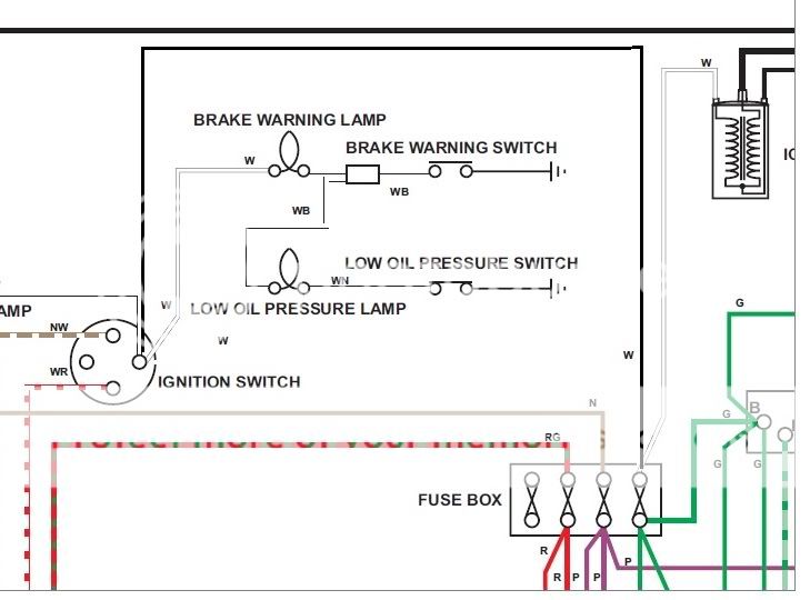
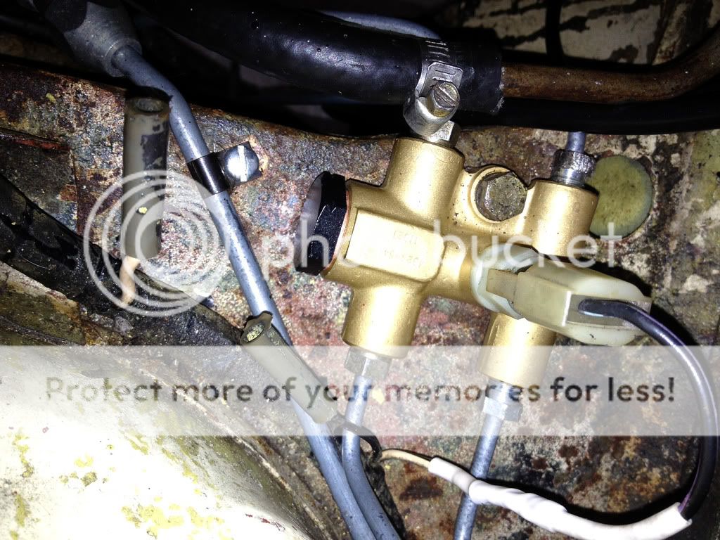
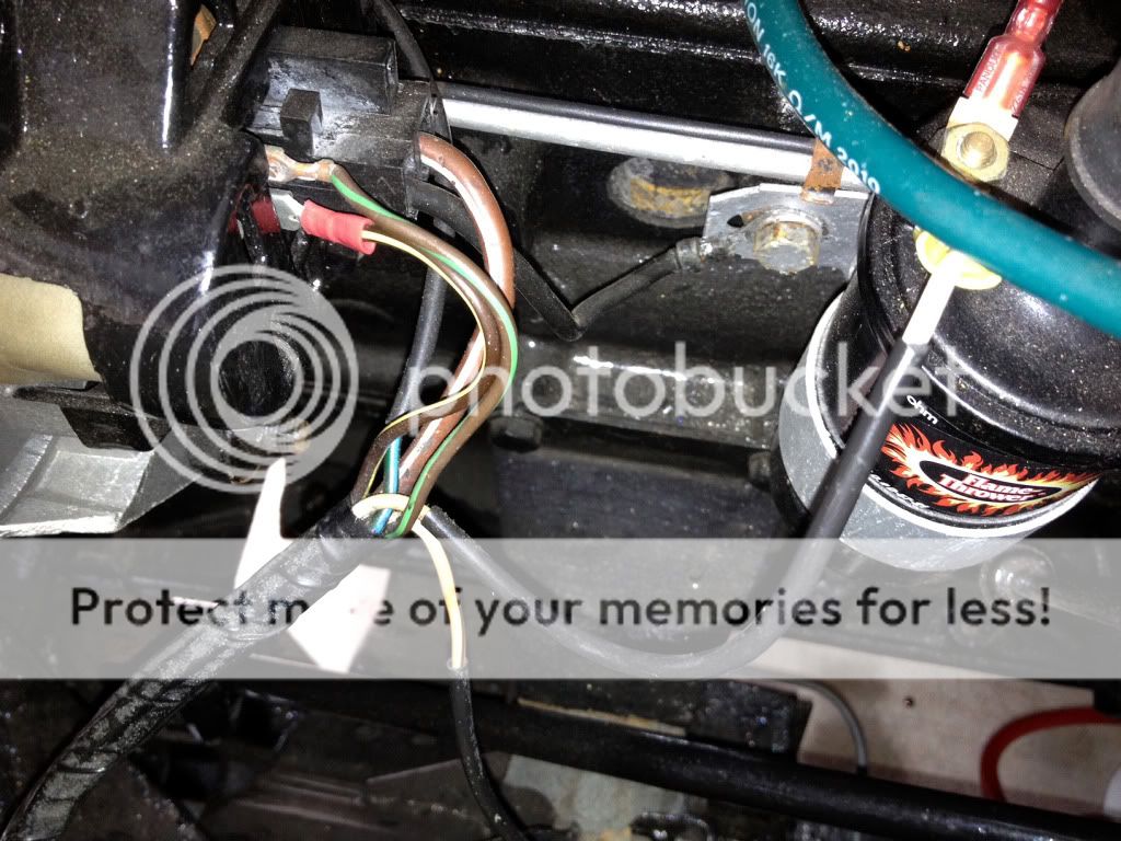
The two wires leading to the PDWA, from my car's harness, are just bare on the ends. From the looks of the PDWA switch, it appears that there ought to be some kind of plug or fitting that the two wires should be connected to and then that connector would be pushed onto the switch. Make any sense?

I have know idea if this is correct as whatever should be there is gone from my car and I can't find a good picture or diagram anywhere. There is one at Buckeye Triumphs but I can't quite make out what I'm looking at or what I need.

Thanks - Bob
 

TR3driver

Great Pumpkin - R.I.P
Offline
RagTopMan said:
From the looks of the PDWA switch, it appears that there ought to be some kind of plug or fitting that the two wires should be connected to and then that connector would be pushed onto the switch. Make any sense?
Prezactly.

There were at least two different styles of connector, AFAIK both have been NLA for a long time. Sorry for the poor photos, not mine. This one was grabbed from the Buckeye Triumphs web site:
 

Attachments

  • 29251.jpg
    29251.jpg
    23.5 KB · Views: 507

TR3driver

Great Pumpkin - R.I.P
Offline
Here's what I think is the later style, from a eBay auction:
 

Attachments

  • 29252.jpg
    29252.jpg
    39.5 KB · Views: 493

dklawson

Yoda
Offline
The switch itself only provides a path to ground for the wires connected to the switch. So... even if you cannot find the plug you need, you can use female sockets from a Molex type connector (should be available at Mouser.com and others). Crimp those onto the end of the wires and push the sockets over the pins in the switch.

That said, I thought someone had posted about a similar switch used on a Ford or GM product that used a nearly identical plug that would work. Hopefully someone else reading this post will remember the same and be able to tell you what part to ask for.

EDIT: This is not what I was thinking about but... the link below is for a plug used with the second switch type that Randall posted the picture for.
https://www.ldparts.co.uk/shop/shop.php?c...a478a0577be22eb
 

dklawson

Yoda
Offline
Rather than edit again, I'll make a new post. This time searching gave me better results.

Ford used a very, very similar switch that may even fit the British PDWA. It is Ford part number: C8AZ-2B264-A
If you google for the switch by part number it is still available. The link below lists vehicles where the Ford switch was used.
https://www.drakeautomotivegroup.com/Store/Product/C8AZ-2B264-A.aspx?wid=141
With a little leg work you may just find that Ford also has a mating connector for the switch.

Failing that, on another link I stumbled on, it was suggested that you can take a female spade lug connector and open up its end with needle nose pliers so the female crimp connector will push onto the two posts inside the PDWA switch. Since those two posts on the PDWA are tied together in the switch, the spade lug solution will work fine. However, there will not be any "seal" around the connection so a bit of dielectric grease may be helpful to prevent corrosion.
 

Brosky

Great Pumpkin
Offline
You can see more about it at my site here: https://www.74tr6.com/pdwa.htm

Either side of that switch is usable, or in other words, both terminals on top lead to the same pin on the bottom , so use one or both, it will be the same.
 
OP
R

RagTopMan

Senior Member
Offline
Thanks guys. I'm thinking two female spade connectors are what I am going to end up doing. Finding that connector looks like the proverbial needle in a haystack for sure.

Though I love the hunt, after two years on safari for this car... I need a break!
 

TR3driver

Great Pumpkin - R.I.P
Offline
Brosky said:
Either side of that switch is usable, or in other words, both terminals on top lead to the same pin on the bottom , so use one or both, it will be the same.

Not certain, but I believe the TR250 arrangement relied on the switch to connect the two top terminals together (meaning one of the wires is a ground), rather than relying on the ground through the switch and shuttle. It also used a different shuttle design, which may have something to do with the wiring/plug change.
 

Number_6

Jedi Warrior
Country flag
Offline
Moss Europe has it their site (No. 79: AAU1700A SWITCH, pressure warning £33.95) Although it's a little pricey at about $53.

LHD Brake Pipes & Fittings
 

Brosky

Great Pumpkin
Offline
Just make life easy on yourself and go to NAPA and get a pack of these and one will fit perfectly, as you see below.

Put a little dielectric grease in there an you are good to go. You can add a nice shrink wrap on the wires going into and over the end of it and it will look like a factory plug.
 

Attachments

  • 29256.jpg
    29256.jpg
    132.1 KB · Views: 451
  • 29257.jpg
    29257.jpg
    81 KB · Views: 361
  • 29258.jpg
    29258.jpg
    59.5 KB · Views: 383

Number_6

Jedi Warrior
Country flag
Offline
Well yeah, you could do that for about a buck compared to $53, but Paul, then it wouldn't be concours. :laugh:
 

glemon

Yoda
Country flag
Offline
My car, an early TR250, CD2004L, has a single wire switch, it appears to be original, the wiring harness is original and uncut. Paul that looks like an easy fit for the two prong plug, great idea/find.
 
OP
R

RagTopMan

Senior Member
Offline
glemon said:
My car, an early TR250, CD2004L, has a single wire switch, it appears to be original, the wiring harness is original and uncut. Paul that looks like an easy fit for the two prong plug, great idea/find.

OK. So is that single wire at the switch fitting white with a black stripe?

I was able to aquire a later TR6 plug that has a single wire lead coming from it. It is black with a purple stripe but I obviously could care less as to the color. If I butt the white with a black wire from my harness to the black with a purple stripe lead from the plug I found, I think I will be all set.

Here's what I'm trying to resolve. I've got three wires coming from the harness near the PDWA. One is white with a black stripe, one is solid black, and the other is a thicker solid (off) white. I'm confident the white with a black stripe should be going to the PDWA switch but the other two are a mystery.

Page 91 of Dan Masters' handbook shows this in detail but I still can't reconcile what his diagrams are showing with what wires I have available.

I'll try to post a couple of pictures soon.
 

hondo402000

Darth Vader
Offline
I concur
your 250 shows WB going to the PDWA switch, later models show 73 on show BP wire to the switch, not sure what the other wires go to, if not in use I would tape the ends and wire tie them to the harness and figue out where they go, there is a White Brown that goes to the low oil pressure swtich on your year, and black it most always a ground and I think white is hot, I think switched
you could check that with a Volt ohm meter

Hondo
 

angelfj1

Yoda
Country flag
Offline
RagTopMan said:
glemon said:
My car, an early TR250, CD2004L, has a single wire switch, it appears to be original, the wiring harness is original and uncut. Paul that looks like an easy fit for the two prong plug, great idea/find.

OK. So is that single wire at the switch fitting white with a black stripe?

I was able to aquire a later TR6 plug that has a single wire lead coming from it. It is black with a purple stripe but I obviously could care less as to the color. If I butt the white with a black wire from my harness to the black with a purple stripe lead from the plug I found, I think I will be all set.

Here's what I'm trying to resolve. I've got three wires coming from the harness near the PDWA. One is white with a black stripe, one is solid black, and the other is a thicker solid (off) white. I'm confident the white with a black stripe should be going to the PDWA switch but the other two are a mystery.

Page 91 of Dan Masters' handbook shows this in detail but I still can't reconcile what his diagrams are showing with what wires I have available.

I'll try to post a couple of pictures soon.

ragtopman:

I also have an early TR250 CD1510LO, but the production point doesn't matter as all TR250's and 1969 TR6 models used the same wiring loom.

See attached DMasters diagram, the British wiring convention is white for ignition switched loads.

Note, there was a wire missing in my copy of the diagram. I added a wire (shown in black but marked W for white) between the ignition switch and fuse block.

So, any wire that is white feeds a load that is only energized when the ignition switch is in the ON position. For your TR250 (and mine) this means:
1 alternator warning lamp {white}
2 ignition coil {white}
3 brake warning lamp(PDWA){white/black tracer}
4 low oil pressure lamp {white/brown tracer}

Except for 1, these wires exit the loom at about the same point. In addition and as you stated there is a black wire (always ground/earth) HTH

Cheers, Frank

BRAKES.jpg
 
OP
R

RagTopMan

Senior Member
Offline
Thanks everyone. Here's the newly installed rebuilt PDWA wired to the black/white wire from my harness. The circuit seems to work exactly as described in the Masters handbook. With the key in the 1st position, both the brake and oil pressure warning lights glow dimly (each receiving 6 volts). Within a second or two after start-up, once oil pressure comes up, both lights go out.

I still have the mystery of the solid black and solid white wires, shown in the photo below, that are coming out of the loom near the PDWA.

Anyone with a TR250 or early TR6 have any ideas? I'm going to start a new thread on my final electrical issue, that being an ALT warning light that stays on unless I disconnect the battery. Perhaos that is a hint as to where these wires might belong?

PDWA3.jpg
 

angelfj1

Yoda
Country flag
Offline
RagTopMan said:
Thanks everyone. Here's the newly installed rebuilt PDWA wired to the black/white wire from my harness. The circuit seems to work exactly as described in the Masters handbook. With the key in the 1st position, both the brake and oil pressure warning lights glow dimly (each receiving 6 volts). Within a second or two after start-up, once oil pressure comes up, both lights go out.

I still have the mystery of the solid black and solid white wires, shown in the photo below, that are coming out of the loom near the PDWA.

Anyone with a TR250 or early TR6 have any ideas? I'm going to start a new thread on my final electrical issue, that being an ALT warning light that stays on unless I disconnect the battery. Perhaos that is a hint as to where these wires might belong?

PDWA3.jpg

RAGTOPMAN

<span style="font-weight: bold">Did you read my post?

See #861402 above.

Solid WHITE is +12 VOLTS, IGNITION
Solid BLACK is GROUND (EARTH)

If you have another IGNITION feed that's OK - just tape up the white wire to prevent a short.
Same for the black ground if you dont need it.</span>
 
OP
R

RagTopMan

Senior Member
Offline
I did read your post Frank. I'm just slow to come around to the idea of a lead that clearly looks to have been there for a purpose being taped up and tucked away. Then again, some would say I'm just slow period. :frown:

Here's a shot of the wires emanating from the loom at the alternator. So the white wire (almost entirely encased in black shrink wrap) coming from here and leading to the coil is my ignition source?

alt1.jpg
 

glemon

Yoda
Country flag
Offline
Bob, My TR250 is just that same, I have the white and black wires near the PDWA, I hooked the black to ground, the near the PDWA goes nowhere, I have the white wire nearer the alternator hooked up to the coil like you have as well.

It has me curious, but everything is working as it should on my car from an electrical perspective, so ???? don't know what it was for.

Agree Frank, white is for ignition cicuit sure, but I too feel the white wire wouldn't be there if it didn't have a specific purpose.

Anyway Bob, it appears they were all or at least some made that way.
 
Similar threads
Thread starter Title Forum Replies Date
Got_All_4 TR6 Triumph TR6 PDWA Brake Question Triumph 1
M TR6 PDWA valve Triumph 6
M TR6 PDWA Issue Triumph 5
S TR2/3/3A Pdwa Triumph 6
M TR6 Early vs newer pdwa for Tr6 1975. Triumph 3
SherpaPilot TR6 PDWA Leak Triumph 7
M TR6 Pressure differential warning assembly PDWA valve Triumph 4
brgrmyster GT6 What's the purpose of the ball bearing in the PDWA switch? Triumph 1
sparkydave PDWA rebuild Spridgets 13
I PDWA switch rebuilding help Triumph 12
Scott_Hower PDWA; tips for getting the shuttle out of it. Triumph 3
I TR6 TR6 PDWA switch help please Triumph 10
hondo402000 wanted Hazzard bezel or PDWA warning bezel. 71 TR Triumph 0
hondo402000 PDWA Rebuild Triumph 18
dklawson PDWA Switch Terminals & Rebuild Triumph 6
T Is the PDWA selt-centering? Triumph 6
MTribe PDWA leak - how to fix? Triumph 6
Brosky PDWA & Rheostat Rebuild pages competed Triumph 6
red_tr250 Stag Stag PDWA vs TR6 Triumph 2
D PDWA switch? Triumph 15
jjbunn PDWA Seal Bolt Removal Method Triumph 12
jjbunn Brake Master Cylinder and PDWA Questions Triumph 11
B PDWA switch query Triumph 2
Brosky PDWA De-Mystified Triumph 29
A Permanent fix for PDWA brake switch Triumph 19
SpannerMan TR6 Source for TR6 pressure switch [pdwa] rebuild kit? Triumph 21
Scott_Hower Sectioned PDWA photo MG 24
G Gonzo PDWA valve Triumph 30
71tr PDWA Valve O-Ring Material Triumph 6
cutlass29 Spitfire spitfire mk3 '70 brake pressure switch pdwa Triumph 1
Scott_Hower Radiator back in and brake PDWA leak MG 3
77MidgetMkIV PDWA rebuild Spridgets 7
tr6web TR6 PDWA switch TR6 Triumph 5
T TR6 Alternator wiring Triumph 6
B Land Rover Series 3 Wiring Diagrams Rover / Land Rover 0
J TR2/3/3A Wiring Triumph 11
71TR6 TR2/3/3A A TR3A wiring question Triumph 17
T 1971 Fuse Box and Wiring Triumph 7
tahoe healey Wiring Diagram for Fog Lights Austin Healey 12
P Wanted Wiring scraps Triumph Classifieds 14
olarson TR2/3/3A Horn Replacement Wiring Triumph 7
Sopwith_Camel horn relay wiring Jaguar 3
luke44 TR2/3/3A Calling all Wiring experts TR3 Overdrive Wiring ver A or ver B or are they the same? Triumph 8
K TR2/3/3A Wiring a voltmeter gauge to replace the ammeter. Triumph 1
B Steering Column Wiring/Sealing Austin Healey 1
timsgolf Coil Wiring Austin Healey 20
T Spitfire 67 MK2 Wiring Triumph 12
Joel Lester TR2/3/3A TR3 Wiper motor wiring and testing Triumph 5
P XJ12 Wiring diagrams Jaguar 1
Scotsman Wiring Diagram for 1966 BJ8 Austin Healey 3

Similar threads

Top