• Hey Guest!
    BCF is a FREE resource for the Little British Car community. I just did a little math and found that less than 1% of the registered members appreciate this forum enough to support us with an account upgrade. We do not "require" you to pay to play here, but if you find BCF helpful, appreciate no pop up ads, and want to ensure we stay online - Consider supporting us with an "optional" low-cost member upgrade. There are some benefits to upgrading!
    **Upgrade Now**
    (PS: Subscribers don't see this UGLY banner)
Tips
Tips

TR5/TR250 TR250 Alternator Warning Light

RagTopMan

Senior Member
Offline
My alternator warning light glows whenever my battery is connected. This is with the ignition switch in the verticle/key out position.

When I turn the key to the IGN position, where one <span style="font-style: italic"> </span> should <span style="font-style: italic"> </span> see the ALT warning lamp illuminate, mine turns off and stays off when I rotate the switch further to the start position. Other warning lights, brake and oil pressure, that illuminate with the key in this position work as they should.

The only way I can make the alternator warning light turn off is to either disconnect the battery each time I park the car or unplug the white wire at the back of the ignition switch which leads to the lamp.

Now with the white wire at the ignition switch disconnected, I have confirmed that I have power at this wire when the battery is connected and switch is to verticle/key out. I'm thinking this should not be the case.


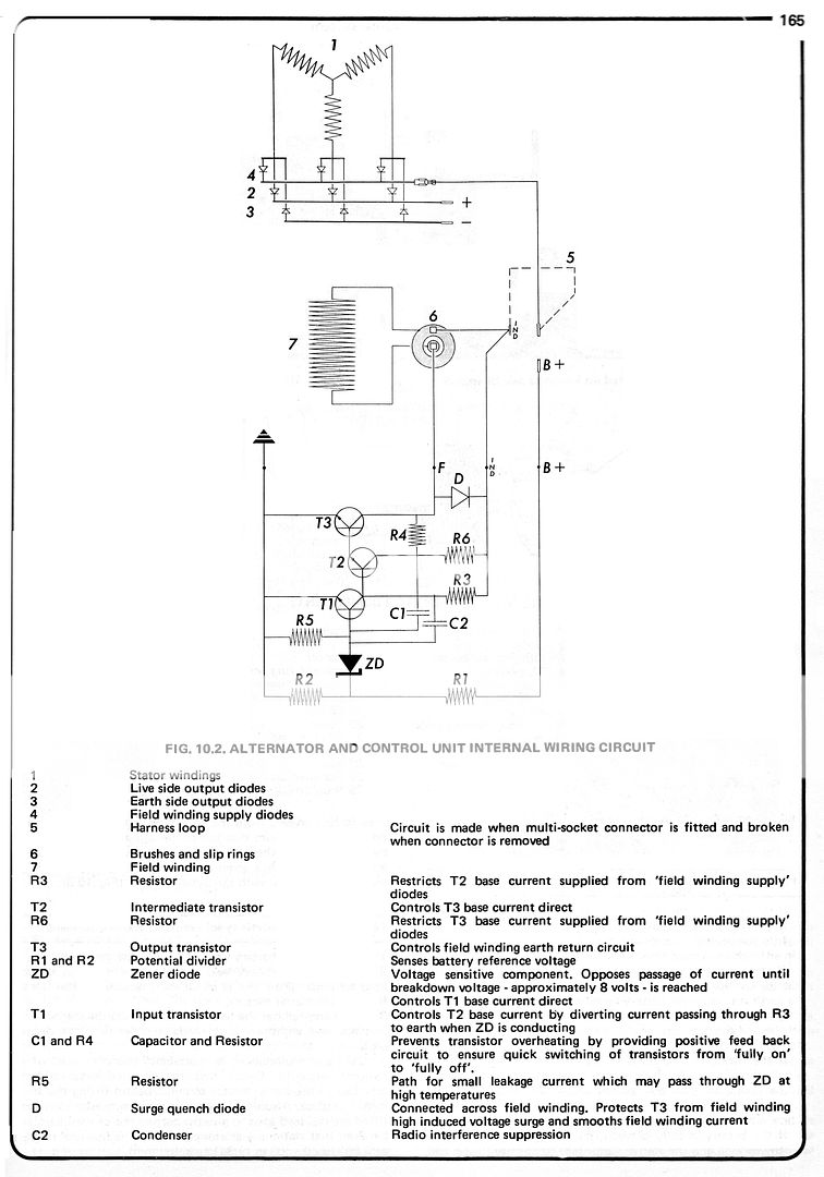
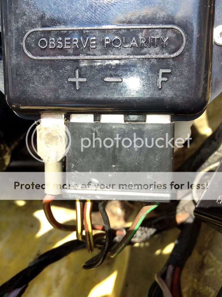
Alternator (original Lucas 15AC) has recently been rebuilt and re-bench tested, to be certain, just last week. All wiring is correct to the regulator, ie: IND (NY) and F- (NG)leads to their correct location on the regulator. The regulator is also new (makes no difference which one I have connected, old or new, in concerns to this issue).

Any ideas? This is my last electrical issue and I'm so eager to put it behind me!
 
A bad regulator might do this, I think. The only other possibility I can come up with is that the wire to the lamp might be connected to the wrong terminal on the switch, but then I wouldn't expect it to go out when you turn the key to the ign position.
 
The 12v you see on the white wire with it disconnected from the switch is likely being fed backwards through the warning lamp, from the NY wire. If you want, you could double-check that the NY wire has power on it (not necessarily full 12v but more than zero) with the key off and the engine stopped.

Reconnect the white wire and pull the 4-pin plug off of the 4TR regulator module. If the light goes out, you have a blown diode inside the module (which pretty much means replacing it). If it doesn't go out, then try disconnecting the brown/yellow at the IND terminal on the alternator. If it now goes out, there is a bad diode inside the alternator (which may not have been detected during the bench test).

If the light still doesn't go out, then there is a short at the 4-pin plug, or somewhere along the wiring.

I hate new parts that are bad, but unfortunately it happens a lot these days. And "rebuilt" is even worse.
 
TR3driver said:
The 12v you see on the white wire with it disconnected from the switch is likely being fed backwards through the warning lamp, from the NY wire. If you want, you could double-check that the NY wire has power on it (not necessarily full 12v but more than zero) with the key off and the engine stopped.

With the key off/engine stopped, there is power on the NY at the IND alternator spade, at the + spade at the regulator, and at the warning lamp bulb holder. I take it this should not be the case?

I remember pulling the NY from the alternator with no effect on the warning lamp but never tried disconnecting the wiring to the regulator. For this test, should I only pull the NY or the whole multi-wire block? The latter is much easier.
 
RagTopMan said:
With the key off/engine stopped, there is power on the NY at the IND alternator spade, at the + spade at the regulator, and at the warning lamp bulb holder. I take it this should not be the case?
Right. With the engine stopped and the ignition off, the NY wire should have 0v.

<div class="ubbcode-block"><div class="ubbcode-header">Quote:]I remember pulling the NY from the alternator with no effect on the warning lamp but never tried disconnecting the wiring to the regulator. For this test, should I only pull the NY or the whole multi-wire block? The latter is much easier.
[/QUOTE]
Either one is fine, but as you say, it's a lot easier to pull the whole connector.
 
TR3driver said:
RagTopMan said:
With the key off/engine stopped, there is power on the NY at the IND alternator spade, at the + spade at the regulator, and at the warning lamp bulb holder. I take it this should not be the case?
Right. With the engine stopped and the ignition off, the NY wire should have 0v.
To be specific, you are referring to 0v on the NY at the warning lamp, correct? I should have power on the NY at the IND alternator connection and at the regulator, but not at the lamp, with the ignition off and engine stopped of course.
 
Well, no, the entire length of NY wire should have the same voltage at all points. So, 0v at the IND terminal, and 0v at the regulator, and 0v at the lamp.
 
Theoretically shouldn't there be a little voltage drop at the end of the wire.
Maybe splitting hairs?
Course , you'd need a pretty good meter to see it??
 
There would be a (tiny) voltage drop only if there were current flowing through the wire. But in this case, no current, so no voltage drop.

With the key on and the engine stopped, there would be a bit under 0.2 amps between the dash light and the regulator. Assuming the wire is roughly 16 AWG and 5 feet long, the drop would be something like .0004 volts. Not something you're likely to notice.
 
First off, thanks to those who have helped out thus far.

I finally had the chance to go out the car to resume the diagnosis and here are my findings (sorry, I cannot state voltage as my AWOL neighbor conveniently has my meter, so I am using a simple test light):

With the battery connected, key out/engine off, there is definitely power at the NY wire at all points (IND connector at alternator, at the regulator, at the bulb holder. I am admittedly totally confused as to how power should flow in this circuit but with the NY wire pulled from the alternator spade connector, there is no power at the IND alternator spade. But there is power on the disconnected NY wire.

Pulling the NY wire from the alternator does not cause the indicator lamp to go out.

Pulling the wire block containing the NY wire from the regulator, does turn the indicator light off.

I've replaced the regulator with a new/unopened one I had as a back-up (obtained from BPNW) and, after rechecking the connections to be correct, I plugged up the wiring. The indicator light began to glow again just as with the regulator I have had installed.

One other thing I have done, quite by accident, is to disconnect the 4th wire at the regulator (the one not clipped into the connector block). The diagram shows this to be NR but I cannot find any tracer on it. With this wire unplugged from the B+ (actually, unmarked on this particular regulator) spade at the regulator, the alternator light DOES go out. Again, this is with the key out and engine not running. When I turn the key to the first stop; all warning lights glow as they should, including the alternator warning lamp. Once the engine is started, the alternator lamp goes out as it should. So this wire being disconnected does leave me with a properly functioning lamp.

If it helps, this 4th/independant wire, does test to have constant power whether the engine is running or not.

???
 
Hmm, I was under the impression that the connector block contained all 4 wires.

Try hooking things back up and checking the voltage on the "-" pin at the regulator (right on the pin, with the wire/connector attached if you can). A bad ground is the only way I can see that a good regulator would put out power on the + terminal.

The way it should work:

1) Key off, NY wire should be at ground, no current flowing. The NR (which may actually be only N/brown in spite of what the drawings say) should be hot, but only a tiny amount of current flows through it into the regulator and through some resistors inside.

2) When you turn the key on, some current flows through the warning light on the dash, the NY wire, and into both the regulator and the field winding. The voltage is quite low, so the dash light is on, but there is just enough current to activate the regulator, which pulls the NG wire to (nearly) ground, completing the circuit through the field winding; and to provide a small magentic field in the alternator rotor.

3) When the engine starts, the small and now spinning magnetic field creates some output voltage, which gets fed back into the field to provide more field current. The increased current produces increased voltage and the output rapidly comes up until either the battery is being charged at full rate, or the voltage regulator senses that the voltage has risen too high and interrupts the circuit through the field (by no longer grounding the NG wire). At this point, the IND terminal should be at battery voltage (roughly), providing power to the regulator to run it's internal electronics. The dash lamp is out because it compares the NY wire to the white wire, which is also hot (because the key is on).

I know I've got some Lucas documentation somewhere, but I couldn't find it last night. But here is the internal schematic from the Haynes manual:

15ACalernatorTR250diagram.jpg


Click here for the full-size version, which you can download to your hard drive if you like. Note that some of the lines appear to be missing in the image above, but they are actually in the full-size version.
 
Thanks Randall, I certainly have a better understanding of how the circuit should work... unfortunately mine still does not!

I've checked the "-" pin at the regulator, with the key out/engine off and the connector attached and I do not have power there. At the regulator, I have power at the unmarked pin where the "seperate" wire connects (NR in the diagram but solid N on my car) and I have power at the "+" pin (NY wires connect here).

I've attached a photo showing my wiring at the regulator. From left to right:

"Unmarked" terminal (what I assume is B+, as shown in the diagrams) = N wire

"+" terminal = 2 X NY wires

"-" terminal = B wire

"F" terminal = NG

regulator1-1.jpg


At the alternator, the NG is connected to the "F-" terminal and the NY is at the IND terminal.


alt2.jpg
 
I thought I should note that the terminal locations on these currently available regulators are different than what was originally found in the car and differ from what the wiring diagrams show. I had to pull the wires from the connecting block and rearrange them to match what seemed to be correct for the new regulator.

Since the operation of my warning light circuit seems to be exactly opposite of correct (ie: when the key is turned to the 1st position, the light goes out, rather than turning on, and when the ignition switch is verticle/key out, the light remains on)... any chance I've fouled up the wiring?

Wishful thinking I know.
 
RagTopMan said:
any chance I've fouled up the wiring?
Seems possible to me. At this point, the only other explanation seems to be that your new regulator is defective.

<span style="text-decoration: line-through">Your photo of the regulator didn't show for me ... is there any chance that only the markings are different and the pinout is actually the same?</span>

Oops, never mind, I see it now.

I'd check one myself, but I traded the only TR250 regulator I had to a friend who had gotten a Stag regulator by mistake. Both considered to be "4TR", but the Stag version has only 3 pins and slightly different circuitry inside.
 
Hmm, well, I'm confused. Best explanation I can find at the moment is that the regulators being sold don't work the same as the original. I see that TRF has the original listed as "NLS" without a cross reference, which usually means they could not find an acceptable equivalent. (Other vendors are sometimes less picky about what is "acceptable".) Might be time to ask BPNW if they have installation instructions available.

What does your ammeter do if you start the engine with the wire to the unmarked terminal disconnected?

PS, I see where BPNW sells the same regulator for early MGB. I'll check my MGB manual when I get home tonight (but that probably wont' be until after 9 PM).
 
TR3driver said:
Hmm, well, I'm confused. Best explanation I can find at the moment is that the regulators being sold don't work the same as the original. I see that TRF has the original listed as "NLS" without a cross reference, which usually means they could not find an acceptable equivalent. (Other vendors are sometimes less picky about what is "acceptable".) Might be time to ask BPNW if they have installation instructions available.

What does your ammeter do if you start the engine with the wire to the unmarked terminal disconnected?

PS, I see where BPNW sells the same regulator for early MGB. I'll check my MGB manual when I get home tonight (but that probably wont' be until after 9 PM).

Funny, I just got off the phone with Layton at BPNW. He claims they've sold about half of their lastest batch without any complaints that he can remember. And my two were in that batch. I was inquiring as to whether any of the markings might be inaccurate as to the actual wiring inside the regulator. Grasping I know but I was hoping maybe a terminal reversal would solve the problem.

With the wire to the "unmarked/B+" terminal disconnected and the car running, the ammeter indicates alternator charging. Key to the first position has the indicator light coming on, which goes out within a second or so after start up.

I think the Stag and Jaguar E type used a similar 4TR regulator except that it only had 3 terminals. The missing one was the "B+". Grasing again I know... as I don't own either of these cars!
 
RagTopMan said:
He claims they've sold about half of their lastest batch without any complaints that he can remember.
Now the fun part is to call back in a few months and see if anyone (you) has complained :devilgrin:

<div class="ubbcode-block"><div class="ubbcode-header">Quote:]With the wire to the "unmarked/B+" terminal disconnected and the car running, the ammeter indicates alternator charging. Key to the first position has the indicator light coming on, which goes out within a second or so after start up.[/QUOTE]
Sorry, I should have been more specific. My question is whether the regulator is actually regulating the voltage, meaning the charge should taper off after a bit. You might need to go for a drive to see it taper off, depending on how discharged your battery is. Or you could pay a visit to the local O'Reillys and ask them to test it for you. Mine will cheerfully do it for free, which I think is a national policy.

<div class="ubbcode-block"><div class="ubbcode-header">Quote:]I think the Stag and Jaguar E type used a similar 4TR regulator except that it only had 3 terminals. The missing one was the "B+". [/QUOTE]
Yup. Basically, instead of a diode trio inside the alternator, they used a relay that ran from a special AC output from the alternator. When the AC output got over a certain voltage, the relay would close and provide full battery voltage to the field & "+" terminal on the regulator. The "+" terminal both provided the voltage sense input, and powered the regulator circuit (meaning it performed the "B+" function as well).

Since your regulator seems to be passing voltage from the unmarked terminal to the "+" terminal, I am thinking that the unmarked terminal is something else. If that is true, the regulator should regulate with it disconnected. But the orignal TR250 regulator would not limit the voltage if the B+ line was disconnected, hence the test.
 
Well, I'm throwing parts at it now... I just ordered ANOTHER new regulator, this time from Moss. More than twice as expensive as what I have from BPNW so surely it will solve the problem. :wall:

Should be to me by tomorrow. I'll for sure let you know what happens.

All this because I am a slave to originality. Oh how strong the drive is to go with one o'dem new-fangled, internally regulated alternators I've heard so much about... :wink:
 
Well if it worked before you replace the VR and didnt work after you replace it, I can only assume, then either you got wires crossed or the VR is defective

its easy to get wires mixed up, I know, thats why I take the handy Iphone and snap a pic of the work I am doing so I have a pic or pics as reference

good luck

Hondo
 
Similar threads
Thread starter Title Forum Replies Date
Marvin Gruber TR5/TR250 TR250 Alternator Triumph 13
angelfj1 TR5/TR250 TR250 - Alternator Upgrade - Questions Triumph 5
J For Sale Set of Dayton 72 spoke chrome wire wheels for TR6 / TR250 Triumph Classifieds 1
angelfj1 TR5/TR250 TR250 - Lucas 4ST Starting Solenoid-Mounting Location/Details Triumph 2
angelfj1 TR5/TR250 TR250 Need Help identifying wires (2 - black) feeding starting solenoid Triumph 6
Got_All_4 For Sale TR6 TR250 TR4 parts for sale Triumph Classifieds 2
T For Sale Excellent Original 1968 TR250 Frame with Engine & Transmission Triumph Classifieds 6
glemon Wanted TR250 Wheels Triumph Classifieds 1
conan69 TR5/TR250 TR250 seats Triumph 1
9 For Sale Magnetic Aluminum Alloy Fuel Cap for TR250 and pre-1970 TR6 Triumph Classifieds 2
9 TR5/TR250 What is this? Appears to be aluminum fuel cap for TR250 and early TR6 Triumph 13
angelfj1 TR5/TR250 Starting a TR250 that's been sitting for 10 years Triumph 12
angelfj1 For Sale TR3, 3A and TR250 Parts for Sale Triumph Classifieds 6
Retired2020 TR250 steering column bushing Triumph 2
Retired2020 TR5/TR250 TR250 smith gauge Triumph 7
S TR5/TR250 "New" TR250 on the horizon Triumph 0
apbos TR5/TR250 TR250 rolling chassis and body for sale Triumph 3
DocDup1 General TR TR6/TR250 Steel Wheels Triumph 3
DocDup1 For Sale TR250/TR6 Steel Wheels Triumph Classifieds 5
MadRiver TR5/TR250 TR250 Radiator Cap Recommendations Triumph 1
Got_All_4 TR6 Routing Speedo cable for a J type tranny in my TR250 Triumph 4
C TR5/TR250 Tr250 registry Triumph 6
Got_All_4 TR6 Oil in the coolant in my TR250 Triumph 6
oldbagpipe For Sale '69 TR6/TR250 Seats now available Triumph Classifieds 0
Gliderman8 General TR Need clarification on Triumph Competition Preparation Manual TR250 TR5 TR6 Triumph 4
S For Sale Triumph TR250 Factory Workshop Service Manual on CD/ROM – 1968 Models Triumph Classifieds 0
K TR5/TR250 TR250 question [Not asking for a friend] Triumph 17
T TR5/TR250 TR250 wiper switch and motor Triumph 1
T TR5/TR250 What lubricant for TR250 wiper box and cable? Triumph 2
glemon General TR TR250 Steering Wheel Options Triumph 6
P Wanted WANTED To Buy a TR4 or TR250 Triumph Classifieds 3
T For Sale TR4 TR250 Rear Fenders Triumph Classifieds 2
T TR4/4A TR4A/TR250 what are they worth Triumph 8
M Wanted Wanted TR4A/TR250 passenger side front fender Triumph Classifieds 0
M Wanted WANTED TR4A or TR250 fendet Other British Classifieds 0
busybrit Wanted TR4, TR4A, TR250 Rear light WANTED Triumph Classifieds 0
glemon TR5/TR250 Stumped TR250 Running Rough--Follow Up Triumph 3
glemon TR5/TR250 Stumped TR250 Running Rough Triumph 8
J For Sale Triumph tr6 tr250, tr5 parking brake improvement kit Triumph Classifieds 1
R Wanted TR4A / TR250 Center Console Triumph Classifieds 1
B TR5/TR250 Registry for TR250's? Triumph 1
brgrmyster TR5/TR250 1968 TR250 original emissions lines Triumph 0
RobT For Sale Triumph TR250 - $32K Triumph Classifieds 2
TRopic6 For Sale Flywheel for TR250/'69 TR6 Triumph Classifieds 0
B Wanted TR250 passenger seat Triumph Classifieds 0
M_Pied_Lourd TR5/TR250 Started my TR250 Restoration Project..... Triumph 16
T TR5/TR250 Original TR250 sun visors Triumph 0
glemon TR5/TR250 TR250 Prototype Triumph 10
flylear45 TR5/TR250 TR250 resto project log Triumph 12
M TR5/TR250 No spark on TR250 Triumph 17

Similar threads

Back
Top