• Hi Guest!
    If you enjoy and benefit from your participation at British Car Forum, please consider supporting our efforts with a subscription.

    There are some perks with a member upgrade!
    **Upgrade Now**
    (PS: Subscribers don't see this banner)
Tips
Tips

TR2/3/3A 1960 TR3A starting chassis work

Frank Canale

Jedi Warrior
Silver
Country flag
Offline
I have decided to change my plan of attack. My metal forming skills still need some work so I am starting on the chassis.
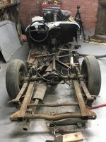
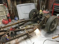
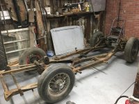
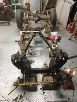
The back half is off.
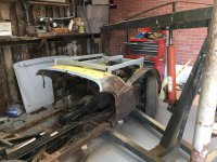
The front clip is ready to take flight.
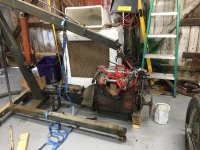
Time to take the motor out. The motor is out. Time to clean up.
The good news is the motor started no problem after sitting for a little over a year, the frame disassembly went really well.
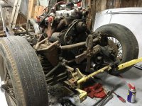
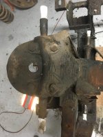
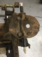
The bad news is I have discovered more frame damage than originally thought. There are two cracks on the back side of the spring tower at the bottom. It appears that someone has done some welding around this area but not to the cracks. I do not see any bulging of the frame rails. The diagonal brace that goes to the frame rail is not bent but does have a lot of rust damage to be repaired where it attaches to the frame. I am going to take my time and start the frame measurement process that is in the service manual. This week will be cold and will slow the work in the shop. If it was easy every body would be driving one. Frank
 

Attachments

  • IMG_0170.jpg
    IMG_0170.jpg
    86.1 KB · Views: 366
  • IMG_0187.jpg
    IMG_0187.jpg
    82.9 KB · Views: 334
  • IMG_0189.jpg
    IMG_0189.jpg
    94.1 KB · Views: 326
  • IMG_0191.jpg
    IMG_0191.jpg
    90.4 KB · Views: 326
  • IMG_0190.jpg
    IMG_0190.jpg
    88.8 KB · Views: 332
  • IMG_0194.jpg
    IMG_0194.jpg
    82.6 KB · Views: 327
  • IMG_0197.jpg
    IMG_0197.jpg
    64.9 KB · Views: 326
Hello Frank

Going to be cold next week.

I see you are missing the body mounting points on the outriggers. Did they stay with the inner sills or were they just gone? Looks like my TR2 in England. The supports were bolted to the body but the outrigger tubes had gone.

I built a pair of sturdy stands for the frame. They would hold the frame and engine.

David
Frame stand.jpg
 
Hi David,
The passenger side is the worst of the car and will be the hardest to rebuild. The B post had been removed by the PO. The car came with a doner B post but I can not see that it was much better than what had been removed. The out rigger mounting plates were in such bad shape I made new ones but realized that the body was going to have to come off to get a good way to start measuring and checking the mounting points. I was a little disappointed to find the damage to the front end but after a nights sleep it is no big deal. Many have fixed a lot worse and I am sure the forum will help me along the way. Just a bump in the road. Thanks, Frank
 
My biggest mistake was not taking the bump stop off below the front shock while the motor was still in the car. I will have to come up with a clever way to compress the spring to get it off so i can get the shocks out. After that the removal should be back on track. Another bump in the road. Frank
 
Looks good Frank. Only problem I can see is the steering wheel is on the wrong side!
I started on the chassis first with my car. Ended up making a new cruciform completely and replacing the outer layer of the right hand chasis rail for most of its length. Re made the tubing accross the very front, rebuilt a chunk of the right tower and replaced the right brace behind the tower.

Important to keep it all square and make sure you have all the measurements correct. Welding of different parts can introduce twist so check before and after several times.

Looks like you have a nice place to work in
lionel
 
Not too late to drop the engine and transmission back in to weigh it down while you get to the bump stops. That was a PITA to do with no weight on the frame and I was working with clean rust free hardware as I reassembled the suspension.

David
 
Thanks Lionel, for the first time in my life I have my own shop. When I got my car it was a pole shed with a dirt and gravel floor, no insulation, and poor lighting. Middle of last year I decided it was time to spend a little money if my car had any chance of success. A concrete floor, painted with rust bullet floor coating, 100 amp service run from the house, new LED lights, and the back wall and ceiling is insulated. The back wall is fake brick but that is the look I wanted. It has the feel of an old work shop. Still looking for an air compressor but no rush for that. Hammers and dollies for now air tools later.
 
Frank,
I'm just down the road from you in Florence,AL. I have several Triumphs and a lot of parts if you need something. There are six TR3s here. Have overdrives if you decide you want one.
Marv
 
Hi Marvin, we used to live in Florence early 70’s. I would love to come take a look at what you have. There is not much left of the quarter panels outside lip so I will need something to make a pattern from to make new ones. There are several small pieces I am looking for so I will start putting together a shopping list. I would say mid February on a Saturday. I will stay in touch so the day is convent for you. Thank you for letting me know you have parts and are close. Frank
 
Thank you for the idea David, sometimes you can’t see the forest for the trees. Walked by the motor and transmission still on the crane on the way out last night. It will only take a few minutes to set it back in when I get home tonight.
 
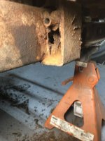
I put the motor back on the chassis in order to remove the bump stops below the shocks. There are 2 bolts holding the bump stop on. The top bolt came off no problem, the bottom bolt did not. The nut came off but the bolt was seized. With a lot of force the bracket rotated down and I could then see the problem. The tube that the bolt goes thru was rusted to the bolt and metal surrounding the tube was gone. No choice but to get out the cut off wheel and cut the head of the bolt off and cut the other side off flush with the bracket now the bracket is off. The driver side came off no problem and no damage. Tomorrow I will start setting up to do a lot of measuring. I stopped and got the frame diagram copied and blown up so I can use it to make notes and develop a plan to start the repairs. It is obvious that something happened to the front passenger side.
 

Attachments

  • IMG_0204.jpg
    IMG_0204.jpg
    54.9 KB · Views: 294
Frank, You are well on your way. Part of me is jealous that you are working on your frame, the rest of me isn't as I don't think I could do that.

Thanks for taking time to document what you are doing...

Oh and BTW, your metal forming skills are better than mine, and quite appreciated. The prop shaft tunnel you made for me was spot on!

Thanks, and keep up the good work

Ron
 
Frank

Do you have a compressor yet?

After I nearly cooked my old Sears 30 gallon compressor doing a bit of sand blasting I got a real one. I could not touch the tank on my sears one it got so hot.
I got an Ingersoll Rand 60 gallon. SS5L5 model from Northern tool. Tractor supply has a similar model cheaper but check the model number to be sure it is the same thing. When I was shopping the tractor supply model was one down from NT.
It has cycled on and off when I was sand blasting. Never fazed it.

David
 
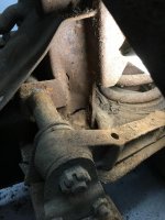
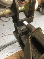
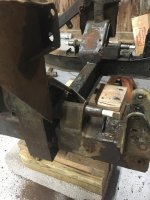
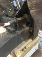
The front suspension is off, in more ways than one. After some initial measurements the shock towers do not appear to be twisted. The upper measurements are correct. The problem is with the lower fulcrum pins. It seems that I am the recipient of a lower fulcrum pin hack job. I don't know if they were replaced or what but both pins were cut out and re welded. The only point on the lower pins that is right is the passenger front. The passenger rear is off and the driver side both are off. I can use some help with a couple of questions. Is the inner top flange of the chassis supposed to be bent up vertical next to the steering box and the idler arm assembly? Picture 5 showes the idler arm side but the steering box side is done the same. looks like it was beat over with a hammer. On the passenger side there is a plate welded to the fulcrum pin and to the chassis behind where the front lower arm mounts, and the same at the back side. These plates are only on the passenger side not on the driver side. Is this correct or is this Bubba making sure that side did not fall off. The upper fulcrum pins are badly corroded and will need replacing.The roadster factory has free shipping till Friday so I am going to see if they have both upper and lower pins. I do not think they are going to have the lower so my next option is Revington or Moss. Has anybody ordered lower fulcrum pins that can make a recommendation? The passenger side spring tower will need to be removed to do the repairs to the bump stop tubes as will as the frame behind the bump stop. I am much more comfortable working on the chassis. Making things straight square and parallel are well defined and easy for me. This is going to take some time but I am looking forward to it. I have not figured out how to keep the text and pictures in order but i will get better as i go along. Frank
 

Attachments

  • IMG_0217.jpg
    IMG_0217.jpg
    85 KB · Views: 294
  • IMG_0214.jpg
    IMG_0214.jpg
    61.3 KB · Views: 250
  • IMG_0218.jpg
    IMG_0218.jpg
    70 KB · Views: 303
  • IMG_0219.jpg
    IMG_0219.jpg
    60.3 KB · Views: 298
  • IMG_0216.jpg
    IMG_0216.jpg
    60.1 KB · Views: 305
  • IMG_0215.jpg
    IMG_0215.jpg
    58.8 KB · Views: 311
Hi Matt, I started in a fab shop right out of high school and always got the jobs of grinding off broken parts so this takes be back to my youth. Thank you for the post about the fulcrum pins. The post describes what was done. They took the easy way out and cut the supporting area around the pin, took the whole thing out, welded it back to the new pin then put it back in and poured the weld to it and that is why the alignment is off. Everybody that takes on these unique cars encounters their own unique challenges.
Frank
 
As far as I can tell from your description, the hammering up of the front inside flanges is NOT normal. Also, the plates on the passenger side are NOT normal. It sounds like you are aware...but just to make sure...concrete slabs are not flat enough to take measurements from as you align your pins and all vertically. Be sure to compensate for that as you go. I used a simple clear tube with water to normalize the vertical measurements.
 
Similar threads
Thread starter Title Forum Replies Date
kodanja TR2/3/3A 1960 TR3A w/TR4 engine, fuel pump replacement Triumph 25
W For Sale 1960 TR3A for sale Triumph Classifieds 0
G For Sale 1960 TR3A for sale $11,999 Triumph Classifieds 0
W TR2/3/3A 1960 TR3A Radiator replacement recommendations Triumph 11
M TR2/3/3A 1960 TR3A--intake manifold-to-SUH6 carbs studs Triumph 3
M TR2/3/3A 1960 TR3A turn signal harness Triumph 6
A TR2/3/3A 1960 TR3A front brake dust covers Triumph 5
F Wanted 1960 Triumph TR3A fuel tank Triumph Classifieds 5
Tinkerman TR2/3/3A Hood stick assembly 1960 tr3a Triumph 7
Tinkerman TR2/3/3A 1960 TR3A engine compression question. Triumph 7
Tinkerman TR2/3/3A Rebuilding SU carbs 1960 TR3A Triumph 3
Tinkerman TR2/3/3A 1960 TR3A post 60000. WON"T START ???????????????? Triumph 8
Tinkerman TR2/3/3A 1960 TR3A Boot rubber seal installation? Triumph 7
Tinkerman TR2/3/3A 1960 tr3a sheet metal fitment Triumph 6
Tinkerman TR2/3/3A 1960 TR3A carpet installation Triumph 5
Tinkerman TR2/3/3A 1960 TR3A Tonneau Capping Installation Triumph 1
Tinkerman TR2/3/3A 1960 TR3A Tonneau Trim Mill board Triumph 10
M_Pied_Lourd TR2/3/3A 1960 Triumph TR3A Trunk Seal Orientation Triumph 6
Tinkerman TR2/3/3A Prepping the grill for installation for my 1960 TR3A Triumph 1
Tinkerman TR2/3/3A Sealing fender to body 1960 TR3A Triumph 15
Tinkerman TR2/3/3A Windscreen mounting tips 1960 TR3A Triumph 2
Tinkerman TR2/3/3A 1960 TR3A Bottom Rubber Seal on the Windscreen Triumph 3
Tinkerman TR2/3/3A Tunnel installation question 1960 TR3A Triumph 11
Tinkerman TR2/3/3A Another Freeby from the past. For a 1960 TR3A Gas Tank Triumph 4
Tinkerman TR2/3/3A 1960 TR3A Holes in the tranny tunnel Triumph 11
Tinkerman TR2/3/3A Carpet underlayment, TR3A 1960 Triumph 10
Tinkerman TR2/3/3A Major oil leak from original oil filter system 1960 TR3A post 600000 series Triumph 3
D TR2/3/3A 1960 TR3a front suspension Triumph 2
Tinkerman TR2/3/3A Front windscreen help needed. TR3A 1960 Triumph 9
D TR2/3/3A fitting windshield/frame to 1960 Tr3a & Brooklands screen removal Triumph 2
Tinkerman TR2/3/3A TR3A 1960 Gas on three out of four plugs ? Triumph 6
Tinkerman TR2/3/3A 1960 TR3A post 60,000 series seat pan covering Triumph 3
Tinkerman TR2/3/3A 1960 TR3A seat tack strips Triumph 1
Got_All_4 TR2/3/3A Finish on a 1960 TR3A Fluid reservoir? Triumph 6
60TR3A TR2/3/3A 1960 TR3A Small Mouth [Huh?] on eBay Triumph 63
M_Pied_Lourd TR2/3/3A 1960 TR3A Mystery G Triumph 24
Tinkerman TR2/3/3A 1960 TR3A Instrument Cluster Ground Post Screw Triumph 9
M_Pied_Lourd TR2/3/3A Restoration of TS 69891LO 1960 TR3A Triumph 36
T TR2/3/3A 1960 TR3A oil leak issue [imagine that!] Triumph 5
T TR2/3/3A 1960 TR3A engine compartment color Triumph 8
PAUL161 TR2/3/3A Colonal Tom Parkers 1960 TR3a For Sale! Triumph 3
T TR2/3/3A 1960 TR3A now with rack and pinion Triumph 22
Tinkerman TR2/3/3A Bulkhead Sealer Plate TR3A 1960 Triumph 3
D TR2/3/3A 1960 TR3A Paint Question Triumph 24
gubba TR4/4A 1960 TR3A with tr4 motor and tranny? Triumph 22
D TR2/3/3A 1960 TR3A Flasher Triumph 7
G For Sale 1960 TR3 fitted black cover. Triumph Classifieds 0
R For Sale 1960 Healey BN7 Oil Pan For Sale Austin Healey Classifieds 2
J Wanted Hood (Bonnet) for a 1960 BT7 Austin Healey Classifieds 0
G For Sale 1960 TR3 A Triumph Classifieds 0

Similar threads

Back
Top