• Hi Guest!
    You can help ensure that British Car Forum (BCF) continues to provide a great place to engage in the British car hobby! If you find BCF a beneficial community, please consider supporting our efforts with a subscription.

    There are some perks with a member upgrade!
    **Upgrade Now**
    (PS: Subscribers don't see this gawd-aweful banner
Tips
Tips

TR2/3/3A Steering control head - how to get the wire down the stator tube -Victory at Last!

jfarris

Jedi Trainee
Country flag
Offline
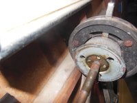
Steve, thanks for re-posting the article about how to re-assemble the control head. Because I don't have the little pins that cancel the signals, it was a bit easier to put back together.

However, I can't get the wires back down and out the lower end of the stator tube when they are wrapped as a bundle. I thought I would ask before I unwrapped them. I took the bullet connectors off and have some new wrap to cover them after they exit the steering box in case I have to unwrap them.

I used a small taped loop for each wire group using some 14 gauge wire and also tried with some super fine safety wire to pull it from the bottom. I do have some shrink tubing over the lower end of the new wire bundle to keep the wrap in place. That may be catching on something near the bottom of the stator tube.

Thanks for all the help!!!
 
Why does this have to be difficult?
The slot on my stator tube was at the top when I started. It's loose now, so I can orient it any way that I want to.
The serrations (?) on the control head tube that go into the stator are now at the 9 o'clock position (looking from the back side), does that matter?
Time for a margarita!
 
I remember there being a 12 and 6 o’clock orientation that could be confused and the system would not operate correctly, 9 o’clock sounds wrong. The way the back piece with the little ear fastens on I believe has to do with 6 and 12 and thus puts stuff out 180 degrees if not correct. The ear does the cancelling so the 2 halves have fit opposite with the opening for the canceller pointing up.

Can you post a picture of where you are at because I cannot visualize it right now? These things are a bear like MD suggested, but rewarding when you get it. I have a couple apart, so I should be able help if I can see yours better.

Steve
 
Thanks for your help Steve. My control head doesn't have the internal cancelling pins, so that is not an issue. The long "ears" are still up at 12 o'clock, aligned with the turn signal controller. These serations (?) that I believe help hold the head correctly in the stator tube was the orientation I was asking about. They are at 9'clock looking from the back side.
CHa.JPG


The control head below is oriented with the blinker control arm at 12 o'clock and the serations at 9 o'clock. Is this correct. I'm ready to try to put the wires back down the stator tube and don't want to have to pull them back out - Marvin's cure was to grease them real good and pull from the bottom.

CHb.JPG


I'll be glad when this job is done!!!
Thanks to all who have helped.
 
here is a picture of and old one in my garage. i think this is what you want
steve
 

Attachments

  • DSCN0292.JPG
    DSCN0292.JPG
    3.3 MB · Views: 33
here is a picture of and old one in my garage. i think this is what you want
steve
Thanks Steve, mine is oriented like the one you have.
Time to try to get that wire pulled through the stator tube again!
 
It was curious when you said the wires were "bundled". I assume you mean they are twisted from turning in the stator over time. They should be straight and untwisted. If you visualize, twisting wires together has the result of making them shorter and fatter. You will likely have to straighten them before you can get them to go through. The most important note is there is no extra room in the tube. The bullet connectors should be staggered, and are cut that way at the suppliers. The wires must be untangled and you cannot allow any to overlap as you feed them into the stator tube. Once they are straight and organized, they should slide through by pushing from the top. If you try to add tape, twine, or anything else to pull them...then they will jam and never go through.

Hope this helps?!?
 
British wire is a different size than USA. The old ones slid right into the tube; the new ones are difficult and require lube and perhaps a wire to pull from end. If you have your original wire system, you can probably see the difference. The old ones were braided and smaller by probably 1/16 over all.

Anyways perhaps that British Wiring Company is hip to this, so I would call them and ask. I bought one on line and it drove me to drink.

Steve
 
It is much easier if the nipples are NOT on the wires when threading the bundle down the tube/
Solder them on lastly. A bit of mechanics wire in the tube pulls them into place,
Mad dog
 
Thanks to everyone who helped. The idea that the gauge of the wires, thus size, have changed over the years is a FACT.
I tried greasing, pushing , pulling, cursing, getting wife involved till I was done and desperate.
I removed the cloth shielding on the outside of the wire bundle. I finally got the very end of the wires to poke out of the bottom of the stator tube at the steering box, but no further.
I had no idea how the stator tube exactly fits or lives in the steering column, but I thought, I have nothing to lose because it is loose and moving because the olive and fitting are off at the bottom. So, I pulled the stator tube out of the top of the steering column. The wires went right through just by pushing them. The stator tube went back into the steering column with no problem. I discovered that the slot in the top of the stator tube and the serations (?) in the tube of the control head are to keep the control head from rotating once everything is back together and it is locked down at the bottom.
Everything is buttoned up and works, I need to refill the steering box with some John Deere "corn head grease" and go for a drive.
Unfortunately, it just occurred to me that I didn't take any pictures. Guess I'm not the best helper for the next poor soul.
On a positive note, I'm about half way finished with my Friday afternoon margarita, may have another today.
!!!Thanks again, you folks are great, you too Basil!!!
 
If the control head can be moved a few inches left to right independently of the steering wheel does that mean that the tube is cracked where the serrated tube fits into it? I am still able to turn the signals on and off by hand but they will not return on their own. About time I addressed this problem. :smile:
 
Try tightening the olive nut at the steering gear first. Have someone turn your steering wheel back and forth as you look at the end of the tube coming out of the steering gear to make sure it is not turning. If that won't fix it, then it is likely that the tube is cracked.
 
Try tightening the olive nut at the steering gear first. Have someone turn your steering wheel back and forth as you look at the end of the tube coming out of the steering gear to make sure it is not turning. If that won't fix it, then it is likely that the tube is cracked.
I will try tightening the nut. Is there a way to fix a cracked tube or is a new one the only solution?
 
Late to the show here, what John said. The control head should not move side to side. That is a hint that the top of the stator tube is broken. Also, once tightened at the olive at the steering box, it should not turn. I saw your other post asking where to find a replacement. Hopefully you can pull it out of the top at the steering wheel. It won't come out of the bottom (steering box) without removing the front apron. The tube has two areas along its length that are expanded in diameter to help locate it in the steering column, so hopefully you can pull or push it out the top. I don't see how you could repair a broken one because there is not room for an inner or outer sleeve. You might also ask Marvin Gruber on this site if he has a spare.
Good Luck!
 
I considered welding my tube that broke, but Grainger had the tube in stainless for about $10, so I wound up just replacing it. Welding could work, but you must be skilled enough to weld the slot back on without bleeding the weld bead inside the tube, as there is already no room for the wires in a new tube. Also, there is very limited space for a weld bead on the outside. You could always grind and/or drill out the beads, but then I would question the strength of the repair.

Guess that's a long-winded way of saying I personally would only weld if I could not find a new tube. I do not think any form of gluing would work at all.
Ok. Good to know I can get one at Grainger I will measure it when I take it out. Did you have any difficulty cutting the slot in?
 
I used a dremel cutoff wheel. It worked, but was slow.
One other thing about the replaced stator tube.....How did you get the 3 anti rattle springs to stay in place? Do you grind down the tube all around slightly so the anti rattle springs sit in the groove?
 
Back
Top