• Hi Guest!
    If you enjoy and benefit from your participation at British Car Forum, please consider supporting our efforts with a subscription.

    There are some perks with a member upgrade!
    **Upgrade Now**
    (PS: Subscribers don't see this banner)
Tips
Tips

TR2/3/3A Accelerator Pedal Advice Needed

PatGalvin

Jedi Warrior
Country flag
Offline
Hi Guys

In a flash of brilliance, I drilled out the pin (item 21) in order to remove the bush (item 20) from the accelerator shaft. This was pretty rusty and I didn't realize that the pin needed to be driven out. So, many years later now, as I'm starting to reassemble, I need some advice how to make this repair. I think this pin (item 21) was a tapered pin that was driven into the bush. I can purchase another pin and install, but it will likely be too loose. I recall that when I drilled it out, I slightly enlarged the hole in the bush and the hole in the shaft. So, any advice on how to repair this? Thoughts much appreciated.

pat

 
Use a spring pin...see link below. drill to a convenient size, and then just drive it in. That's what I used. I forget what size, but what you use will depend on the size hole you have now. You may have to re-drill to fit what sizes are available.

https://www.mcmaster.com/#standard-spring-pins/=ov1n81
 
Yes, mine had been done by the PO with a little nut and bolt.

Cheers
Tush
 
Thanks - these are both great ideas. I'll snap a photo and bore you guys with my ultimate solution! Much appreciated.
Pat
 
BTW, when I did the resto on my car, knowing what a pain in the neck it is to replace those nylon bushings, I re-engineered the whole linkage set-up.

Here's what I wound up doing for the accelerator linkage.

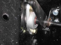
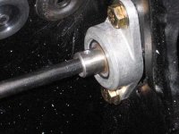
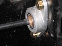
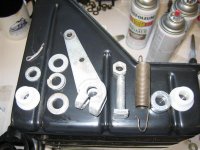
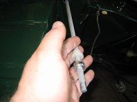
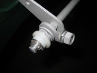
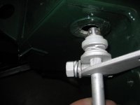
I used a couple of self aligning bushings from McMaster. I did a little re-engineering also. I made a new sleeve where the pins go on the driver's side to connect the cross piece to the pedal. I eliminated the step in the sleeve, and it rides in the new bushing. The pic with the new sleeve doesn't have the pin driven in yet, but to disassemble everything, all I have to do is drive that pin out, then I can extract the pedal from the bushing. You can see that in the last pic. Unbolt the cross piece from the firewall, and you can extract it from the other bushing by pushing into the vacated bushing on the driver's side. Since there's a lot of slop going into that bushing without the sleeve on there, it's very easy to get the cross piece out. IIRC, the ID of the two bushings are different sizes.

The whole system turned out to be very smooth acting and can be taken totally apart in about ten minutes.

19770.jpg19771.jpg19772.jpg
 
Art,
The PS sleeve diameter is the same as the pedal shaft diameter?
Did you have to fabricate (machine) the DS sleeve, or can that be purchased in the desired diameter?
Great photos and description. Thanks

pat
 
Yes, the ID for the sleeve is 3/8", and the OD is 5/8" to fit in the bushing. It's about 1 7/8" long, but that's not too critical. The bushing on the passenger's side is also 5/8" (I first though I may have used a different size), but that is the size of the fulcrum.

I made the sleeve on a lathe and cross drilled it for the pins. That has to be accurate, or the holes in the shafts won't line up.
 
I'd stay away from the "nut & bolt" route, unless you can come up with a bolt with an unthreaded shank that fits tightly in the hole (tight enough you have to drive it in place like a pin). My DPO used a fully threaded bolt and it has waddled the holes until there is a good 3/4" of play in the pedal just from that joint. The threads act like a file and cut away a bit every time you step on the throttle.
 
I'd stay away from the "nut & bolt" route, unless you can come up with a bolt with an unthreaded shank that fits tightly in the hole (tight enough you have to drive it in place like a pin). My DPO used a fully threaded bolt and it has waddled the holes until there is a good 3/4" of play in the pedal just from that joint. The threads act like a file and cut away a bit every time you step on the throttle.


I don't think this sleeve sees any twisting load...isn't it just a lateral locating sleeve?
 
Hmm, maybe it varies by year. On mine, it's a joint between sections of the shaft.
View attachment 29510
 
When I got mine one of those pins had been replaced with a bent over nail. It was painted body color and 'worked' long enough to seriously distort the hole. But looking at the Moss picture, I cant remember which one I have. I do remember drilling it oversized and pressing a split pin in, and am pretty sure it will be difficult to remove with the engine in place. That anti-rattle spring is a spot causing my linkage to hang a little and a pain to lubricate without getting it all over the place. My biggest problem with throttles not coming down to a low idle was the butterfly return springs on my h6s's were not strong enough.
 
Accl Rod Assmbly (1).jpg

Hi Pat and anyone with some advice! I'm working on my accelerator rod and was searching for some advice, I came across Pat's post 10/9/2013, ironically I am in a similar spot.

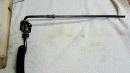
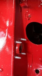
I am going to strip the paint off the rod that was painted by my body guy after he bent it when he worked on the tub, then he (his moronic workers) took it apart because I saw how they installed the rod to the car.. They used large sheet metal screws to attach it to the fire wall that's when I said WTF are you doing?

Any way any advise on getting the pin out #21? Very small punch maybe? (2) Does the BUSH #20 slid on the shaft once the pin is out, or is it supposed to? (3) The rod is not straight it has about a 1/16 of an inch rise in the center portion, should I work on getting that straightened by me some how or a machine shop or is it okay with a slight bow? (4) What should be used to mount the brackets and rod to the body of the car?

Thanks for the help!

Cheers and Merry Christmas! I love those Lights! Bang, crack and pop!
 
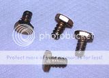
The brackets were originally attached to the body with sheet metal screws. YH7503, hex head #10 by 3/8" ; but you might need to go to 1/2" long if you use modern sheet metal screws (the originals were not tapered).

The (original) pin is a tapered Mills pin, it only comes out one way. Look carefully, you should be able to see the small end. A 1/8" pin punch is the right tool, but you'll need something solid to back it up (like a small socket or nut) and a big hammer to tap it out. My suggestion is to cut off a commercial pin punch so that only 1/8" or so is left at the smallest diameter, to make it much less likely to bend and break while starting to remove the pin. Once the pin has moved a bit, it will get easier and you can switch to using an unmodified punch to drive it the rest of the way.

If you have the earlier version, there are actually two pins, but you only need to remove the one nearer the pedal. With the pin out, you should be able to work the pedal shaft out of the coupling to R&R the bushing.

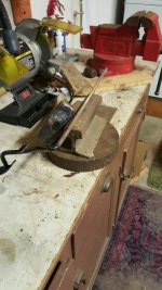
It's probably best to straighten the shaft if you can. The metal is soft, it bends easily. Good chance to practice your blacksmithing skills, if you're so inclined (by which I mean lay it on an anvil or similar and beat back to shape with a BFH). But if the shaft is bent, all that happens is that the bushings have to move around as you press the accelerator pedal. I didn't straighten mine, and the new bushings had a tendency to bind when they got really hot (like being stuck in rush hour traffic on a hot day). But it only took a month or two for them to wear until now they don't bind at all.
 
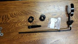
Accelerator Bushing (2).jpgAccelerator Assembly rod damaged holes (1).jpgAccelerator Assembly BFH to straighten(1).jpgAccelerator Assembly B4 (3) LRz.jpgAccl Rod Assmbly (1).jpgAccelerator Assembly Tub Attachment B4 (1).jpg

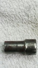
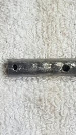
I got out my BFH and used a steel plate and like Randall suggested I practiced my Blacksmithing skills and straightened the shaft. I got the bushing off but it took a lot of convincing. Once I removed the paint I could see where the body shop guys had done a lot of damage to the bushing and the shaft, some deep marks scraped into the metal, smashed holes on the shaft. I think it will be okay but I will need to re drill the holes in the shaft and find some good tapered pins. Then I need to paint it all nicely (black?) and reassemble everything or should I try to see if Marv has a replacement part? The brackets, the ones that hold the nylon bushings, seem to have been drilled out, I'm still not convinced that a sheet metal screw is the right way to go because the ends of the screws are inside the foot well, as they were installed by the body shop they looked lethal! The holes look pretty large so #10s would be too small at this point I think? Maybe some short bolts and lock nuts? Any thoughts? I liked the suggestion for the upgrade in an earlier post but I do not have any good metal fabricating equipment.
Thanks!
 
FWIW, instead of trying to duplicate the original setup with the Mills pins, I reamed the holes (in both the shafts and the collar/lever) so they were round and fitted new slotted spring pins. There may be an issue with the spring pins not being strong enough, but so far (couple of months) they seem to work fine. Seems like I wound up at 7/32" to clean up the damage, but I don't recall for sure offhand.

For the sheet metal screws, my suggestion is to trim them to length. They should only stick out of the firewall by 3/16" or so, and have a flat tip. Should be easy enough to create with a Dremel and a cutoff wheel, or even just a file if you have the patience. These are larger (for the fan shroud on a Stag), but that's how I made them:
 
When I did mine about 9 years ago I wanted it better than original and simpler to replace parts if needed.
Since I have three vertebra fused one of the main things was that I wanted it to not require having to work under the dash to install the cotter key on the passenger side.
I also wanted it to be able to remove and install with the engine in place.
I also wanted it to use common parts.

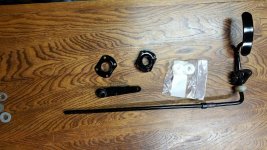
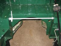
This is what I came up with. After 9 years and 60,000 miles it is still as good as new.

bushing_11.jpgbushing_01.jpgbushing_03.jpgbushing_05.jpgbushing_07.jpg
 
Similar threads
Thread starter Title Forum Replies Date
CARSINC MKIII Accelerator Pedal Spridgets 0
K For Sale TR3 Accelerator pedal assembly Triumph Classifieds 1
M Accelerator Pedal Position Austin Healey 4
K TR2/3/3A TR3A...Kicking accelerator pedal lowers idle? Triumph 20
S XKE Accelerator Ppedal Position Jaguar 2
ArcticOne GT6 GT6 Accelerator Pedal Removal Triumph 8
ArcticOne GT6 Accelerator Pedal - GT6 MKI Triumph 2
ArcticOne Accelerator Pedal Triumph 0
Tinkerman TR2/3/3A TR3A Accelerator Pedal Assembly Triumph 9
Tinkerman TR2/3/3A Accelerator Pedal Assembly ,TR 3A Triumph 6
D MK2 accelerator pedal Jaguar 0
angelfj1 TR2/3/3A TR3A accelerator pedal/shaft Triumph 9
Tinkerman TR2/3/3A Accelerator Pedal Question TR3A Triumph 5
M TR2/3/3A TR3 Accelerator Pedal Triumph 7
Atrus Accelerator Pedal Spridgets 7
mylillooker accelerator pedal cover Spridgets 6
R accelerator pedal feel Triumph 3
Popeye TR4/4A Accelerator shaft install - location of bushing plates? Triumph 2
DocDup1 Wanted TR4A Accelerator Linkage Lever Triumph Classifieds 0
FlyingCat Spitfire Accelerator cable Triumph 4
B LHD to RHD accelerator controls Austin Healey 15
T TR2/3/3A Accelerator Say 1960 TR3 Triumph 11
TomMull Post-War Other Herald: Holy Moly! [Why it took me so long to make the accelerator bracket] Triumph 2
Got_All_4 TR2/3/3A Accelerator shaft question Triumph 2
mgedit TR2/3/3A Link Rod Lengths Accelerator Linkage Triumph 2
J TR2/3/3A accelerator linkage for Weber 45 DCOE Triumph 4
R TR2/3/3A TR-3A accelerator return spring Triumph 9
G Best way to remove accelerator bar part # 106762 Triumph 3
B Accelerator relay rods on RHD Austin Healey 2
bcbennett TR6 TR6 accelerator vibration Triumph 9
bigjones MGB MGB accelerator cable MG 8
I Source for Bugeye accelerator return spring? Spridgets 2
I TR6 TR6 accelerator bar busing replacement help please Triumph 10
KVH TR4/4A Sticking Accelerator or SU Jets: TR4A Triumph 7
TR6oldtimer TR6 TR6 accelerator linkage help needed Triumph 9
H TR2/3/3A TR3 Accelerator Shaft -- Straight or Bent? Triumph 9
B accelerator cable Spridgets 6
Tinkerman TR2/3/3A TR 3A Accelerator Bushing Placement Triumph 21
Tinkerman TR2/3/3A Accelerator Assembly Installation TR3A Triumph 3
Tinkerman TR2/3/3A TR3A Accelerator Assembly Triumph 6
Tinkerman TR2/3/3A TR3A Accelerator Rod Dissasembly HELP! Triumph 1
glemon TR5/TR250 TR250/6 accelerator shaft bush Triumph 5
Jim_Gruber Accelerator Cable termination on carb linkage Spridgets 10
Morris 1500 Accelerator cable Spridgets 7
T Clutch and Accelerator return springs are missing Triumph 6
R Accelerator linkage removal Triumph 2
B Accelerator Cable Spridgets 4
Tinkerman TR2/3/3A TR3 accelerator pedals Triumph 8
Musicman That Dreaded Accelerator Bushing Triumph 5
J Spitfire Spitfire MK3 accelerator bushings Triumph 3

Similar threads

Back
Top